Battery Capacity Monitor Using ADS1115
ADS1115 is 4 channel 16 bit Analog to digital converter. Actually I only need 1 channel to measure the battery voltage but unfortunately ADS1013/ADS1113/ADS1014/ADS1114 module not available at AliExpress and ADS1115 cost about SGD1.80 which is quite reasonable 😁.
The reason I'm looking into analog to digital converter is because the remote control transmitter that I made here, out of analog input to measure battery voltage. I'm not sure if I have enough memory space for it though😕.
I got the schematic below from internet, I posted here for reference. Take note the ADDR pin is pull to ground by 10K resistor, which mean by the default address is 0x48.
ADDR = 0x49 if ADDR pin connected to VCC
ADDR = 0x4A if ADDR pin connected to SDA
ADDR = 0x4B if ADDR pin connected to SCL

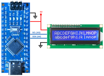
Nothing special on the Arduino Nano connection either. I used 10K potentiometer just for testing purpose. In real application it will be connected to Lithium Ion battery.

The code to read 1 channel are pretty straight forward
With code above, I'm able to read the voltage from 0 to 5V but li-ion battery have capacity theoretically between 3.7V to 4.2V. Thus, I'm using constrain function to ignore anything below 3.7V and above 4.2V. To get capacity percentage, I used map function to map 3.7V as 0% and 4.2V as 100%. But to do this, first I need to multiply voltage by 100 because the map function only work on integer.
Surprisingly it is quite accurate as seen from video below 😁, I thought I need to add some offset or multiply by some constant to get accurate reading.
Do note if you are measuring 2S li-ion, theoretical voltage range around 7.4V - 8.4V. The ADS1115 can only measure up to ~6V, thus you need resistor voltage divider. However you might not get the voltage you want because resistor have tolerance. Especially those from AliExpress, 1% tolerance not necessary to be true 😱. In my case, result was off by ~0.19V which is quite significant for the range that I want to measure. I suggest measure the voltage using multimeter and modify the code accordingly.
Another thing is the LDO dropout is 1.2V. In other word to get 5V, the input voltage need to be at least 6.2V. Which mean the Arduino will still be working even though the battery drop below 7.4V.
Looking at the li-ion discharge profile below, the discharge profile is not linear and change according to the discharge current. The remote control transmitter current consumption is around 200mA (Arduino Nano = 20mA , 1.3" OLED 126x64 = 16mA, E01-ML01DP5 (NRF24L01+PA+LNA) = 130mA and plus margin). Based on the graph below (grey color trace), it drop fast at around 3.2V. It is also drop fast from 4.2 to 4.1. To avoid seeing battery % drop fast, I set the measurement from 3.2V to 4.1V in my finale code 😉.

Comments
Post a Comment